KB: Update schematic component with a new footprint
Solution Details
There are a few ways to update unmanaged file-based schematic components with a new footprint at the design level ad hoc, but it is always best practice to make changes at the component level in your schematic libraries first and then update your schematics from those libraries.
Managed components, such as those in the Altium 365 workspace, are locked, and the footprints cannot be changed ad hoc at the design level. If the changes have already been made at the component level in the server, the design can be updated individually through the 'Out of date' double-arrow button in the Properties panel or, if in batch, through Tools » Item Manager.
Synchronizing to Changed Workspace Content
The rest of this article discusses how unmanaged file-based components placed in a schematic can be associated with a new footprint.
Updating from Libraries:
Schematic components can be updated directly from configured libraries as follows.
From an open schematic document, select Tools » Update from Libraries.
Note: There is an option from a schematic library Tools » Update Schematics, but this does a full replacement of the selected part to all open schematic documents. Use the Update from Libraries option from within your schematic for more control.
Properties Panel:
Footprints can be added to schematic components using the Properties Panel.
Selecting the schematic component, under the Parameters section, click the Add button and select Footprint.
Updating From the PCB:
If a footprint is changed in the PCB document, associated schematic components can have their footprint reference updated by running the command from the PCB document, Design » Update Schematics. This will update the configured footprint in an existing schematic component and will not add a new schematic component.
Using the Footprint Manager:
If the schematic libraries do not have the configured footprint, or you need to set something on the fly, footprints can be managed using the Footprint Manager. You can access the Footprint Manager from an open schematic and select Tools » Footprint Manager.
- To add a footprint
- Select the component in the Component List and click the Add... button.
- To copy a footprint to a component from a similar component
- In the Footprint Manager, select two components in the left pane; one has the footprint you wish to add to the other selected footprints.
- Right-click on the footprint in the upper right pane and select Add to all parts.
A special case is when the schematic component does not have a footprint associated with it, which may happen with imported designs. The process will only work if there is a configured footprint in the associated schematic symbol for the update from the PCB.
In such cases, a temporary footprint can be added from another part if needed, as mentioned above. If there was originally no footprint attached to a component, any footprint can be temporarily added (referred to below in the image as a "temporary"), and then updating from the PCB will change the configured footprint to the correct one. The steps below describe the process:
- Open a Schematic Document in your project.
- Place a component that has a footprint, or use an existing component in the design if one already exists.
- In the Footprint Manager, we will first add a temporary footprint, then we will be able to update to the correct footprint from the PCB to get the correct footprint:
- Select Tools » Footprint Manager
- Sort the listed components by the Current column by clicking on the header.
- Select all the components that have a blank value for Current. This can be done by clicking the first column, then shift-clicking the last (or just control-click to multi-select).
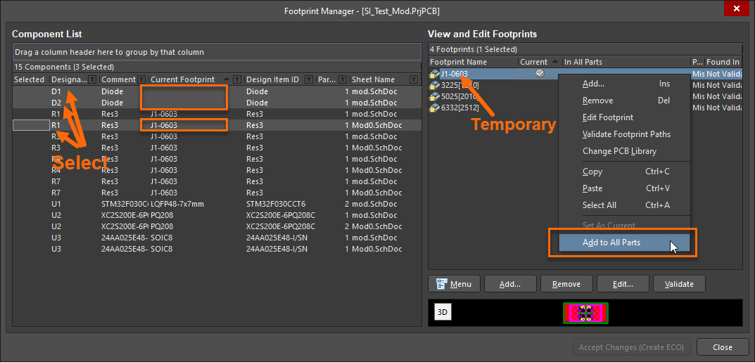
- Be careful not to lose your initial selection; control-click on one additional component with a footprint to add. This will be the temporary footprint we will add to the other parts.
- On the right side of the dialog, right-click on the footprint to add in the upper right View and Edit Footprints pane, then select Add to all parts. See the image below.
- If there is more than one footprint configured for a component, right-click on the footprint you wish to use and select Set as Current.
- Click Accept Changes (Create ECO) and click Execute the ECO...
Updating from the PCB document:
- Now that the components all have a configured footprint, the next step is to open the PcbDoc file.
- It is a good idea to validate Component Links per the steps below:
- In the PCB document, select Project » Component Links
- Ensure that all the footprints are matched. If not, click the Add Pairs Matched by button, ensuring the Designator field is checked. Then click the Perform Update button.
- Update the schematics by selecting Design » Update Schematics and clicking Execute Changes. Once executed, the footprint references in the schematic will match those in the PCB.
Generating a new library from the updated parts on the schematic:
- To generate a new schematic library, select Design » Make Schematic Library. This will include the modified parts with the footprints configured matching the schematic.
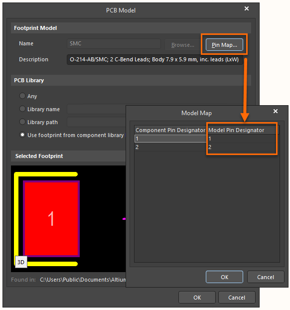
NOTE: Verifying Pin to Pad mapping. At this point, the Schematic to Footprint Pads should be verified, as there is automatically assumed that the referenced footprint Pad will match the schematic designator value. When Editing the schematic component’s PCB footprint, click the Pin Map… button. The Footprint Pin Designator (Pad) will need to be manually checked in the PcbLib or in the Pcb Document, as the Pin Map does not reflect the true value.