KB: Resolving Hole Size Differences in Draftsman Drill Table
Solution Details
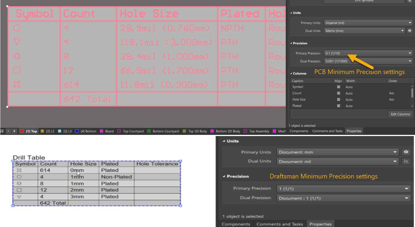
While placing a drill table in the Draftsman document, the hole size values may appear different from those defined in the PCB layout. In some cases, the hole size may even display as 0 mm, leading to confusion or incorrect documentation.
The issue arises due to a mismatch in precision settings between the PCB document and the Draftsman document. The PCB drill table supports a minimum precision of 0.1 mm (1/10), whereas the Draftsman drill table can be set to a minimum precision of 1 mm (1/1). If the Draftsman precision is too coarse, small hole sizes (e.g., 0.203 mm) may round down to 0 mm.
How to Resolve the Issue
To resolve the discrepancy, users should adjust the precision settings in the Draftsman drill table to match or exceed the precision used in the PCB drill table. This ensures that small hole sizes are accurately displayed.
Steps to Adjust Precision Settings
1. Open the PCB Document and place the drill table.
2. Select the Drill Table and open its Properties panel.
3. Check the Precision Settings used in the PCB drill table.
4. Open the Draftsman Document and select the corresponding drill table.
5. Access the Properties panel for the Draftsman drill table.
6. Configure the Precision Settings to match the PCB drill table.
• For example, if the actual hole size is 0.203 mm, set the precision to 0.001 mm (1/1000).
7. Verify the Drill Table Values to confirm that the hole sizes are now displayed correctly.