
KB: Error "Can't load model" when opening a PCB document
Solution Details
The Error "Can't load model (ID = {...}) ..." when opening a PCB document indicates a broken link associated with a 3D model within one of the footprints. Since this footprint can be used multiple times on the board, the issue results in several reported error messages, 51 error messages in our example below. There are three possible sources for a 3D model: Server, Embed Model, and Link to Model. The error occurs when Server is selected as the source, but no valid 3D model from the server or workspace is found.
Since the message does not specify which 3D model is causing the error, identifying and fixing the affected component must be done manually. Carefully review the 3D models on the board, ensuring a valid model is assigned for models where Server is set as the source. If a valid model is selected, no source change is necessary. If an issue is found, update the 3D Model Source within the footprint, update the related components, and synchronize the schematic and PCB.
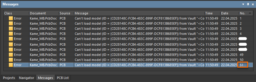
Error when opening a PCB document
Steps to Resolve the Issue
1. Review 3D Models in the PCB List panel: Open the PCB List panel and examine the 3D models on the PCB. Select View all objects include only ComponentBodies. Check the 3D Body Properties to verify whether the source is set to Server and confirm that a valid 3D model is selected. In our example, the affected 3D Body is deleted. Since the source of a 3D body cannot be directly searched, this process must be done manually.

PCB List Panel and 3D Body Properties
2. Locate the affected Footprint: If an affected 3D body is identified, right-click it and select Zoom Selected. Select the associated footprint, right-click, navigate to Component Actions, and select Show CMP in Server to open the component in the Explorer panel.
3. Edit the Component’s Footprint: Select the component's footprint in the Explorer panel, right-click, and Edit to open the Footprint Editor. Select the affected 3D Body. Choose a valid 3D model from the Server, or use the Embed Model option if working with an external 3D model file.
4. Save and Commit Changes: Save the modified footprint and update the related components to the server or the workspace.
5. Update Components in the Schematic: Use the Item Manager on the schematic side to update the components to the latest revision accordingly.
6. Synchronize the PCB: Run Design » Update PCB Document to ensure all footprints are updated.